

Top Highlights
NASA boards experienced ceramic chip-resistor cracking during post-vibration thermal cycling.
Analysis attributed fractures to bending, not defective batches or vibration fatigue.
Board flexure, edge placement, orientation, excess solder, and mounting stresses contributed.
Mitigate risks through careful layout, structural analysis, solder inspection, and thermal testing.
TB 26-10: Printed Circuit Board Assembly Chip Resistor Body Cracking
Chip resistors are common in NASA hardware, but cracks in their ceramic bodies are rarely reported during vibration and thermal cycling. TB 26-10 examines two such failures found during environmental acceptance testing. The cases point to a practical design concern: printed circuit board (PCB) flexure can place large ceramic components under enough stress to crack them.
The failures occurred during thermal cycling after vibration testing. At hot dwell temperatures, each resistor produced an intermittent open circuit. The electrical connection returned when the assembly cooled to room temperature. Both resistors were thick-film, 2512-size components mounted near the edge of a PCB. They were installed in similar positions on two identical boards.
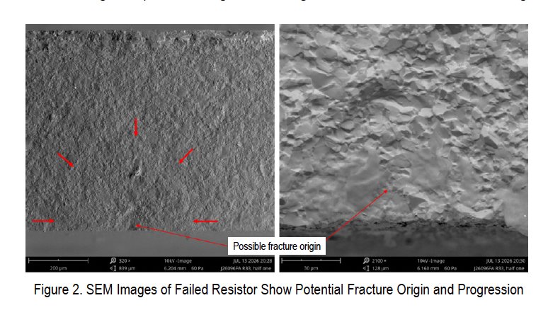
Each resistor had a single fracture across its short axis, perpendicular to its long axis and parallel to its terminations. This pattern was consistent with bending or tensile stress. Neither component showed visible signs of a pre-existing defect.
What the Failure Analyses Found
Because both failed resistors came from the same production lot, investigators initially considered a lot-related defect or damage from vibration. The lot met the requirements of MIL-PRF-55342, and additional testing did not reveal evidence of an elevated defect risk.
Independent failure analyses found no clear crack-initiation site. Optical and scanning electron microscopy also did not identify evidence of fatigue damage. The straight, single-fracture pattern did not match the expected signature of cyclic fatigue. Together, these findings made a defective lot and vibration fatigue less likely explanations.
The analyses did not establish one definitive root cause. Instead, they identified several conditions that could have combined to increase stress on the resistors:
- Placement near the board edge: Large ceramic components can be vulnerable to PCB flexure. In these cases, the resistors’ long axes ran parallel to the nearby board edges.
- Board bow or twist: Manufacturing, installation or mounting can bend a board and load components attached to it.
- Excess solder: Solder extended onto the top surfaces of the resistor terminations. This can make the joint more rigid and transfer board movement into the ceramic body.
- Rigid mounting: A board fixed to a rigid frame may retain or concentrate bowing and twisting stresses.
- Fastener torque and sequence: An unsuitable tightening pattern can concentrate mounting loads near particular components.
These are contributing factors, not proof that any single condition caused the two failures. The bulletin’s central lesson is that component selection alone does not ensure reliability. Board layout, assembly details and mounting practices matter too.
Design and Assembly Practices to Reduce Risk
The bulletin recommends avoiding placement of large ceramic components with their long axes parallel to nearby PCB edges. When layout constraints make edge placement necessary, engineers should use finite element analysis to assess stress and displacement margins. Analysis can help evaluate a design, but it should reflect the board’s actual supports, fasteners and expected loading.
Assembly control is just as important. Keep solder off the top surfaces of component terminations, and follow the part manufacturer’s limits for fillet height. Inspect the physical joints or review clear photographs to confirm that each joint has enough solder for a sound connection without creating an excessive, overly rigid fillet.
Mounting deserves deliberate attention. Engineers and assemblers should consider how board bow or twist may arise during manufacturing and installation. They should also review the mounting arrangement and fastener-torquing sequence for loads that could concentrate near ceramic components.
Finally, the bulletin recommends one to three thermal cycles before vibration testing, including a functional check during the hot dwell. This step can document component integrity in the assembled board before later environmental tests. It does not replace sound design or inspection, but it can reveal an intermittent fault early.
These measures add analysis and inspection effort. Their value depends on the component, board geometry and mission risk. For large ceramic parts near board edges, however, careful placement, controlled soldering and functional testing offer practical ways to reduce the chance that flexure will cause cracking.
The bulletin cites MIL-PRF-55342, MIL-PRF-55342/9 and MIL-STD-202, Method 218, “Board Flex.” Download the PDF through the NASA Engineering and Safety Center bulletin page. For more information, contact NASA Langley Research Center at joel.w.sills@nasa.gov.
Stay Ahead with the Latest Tech Trends
Stay informed on the revolutionary breakthroughs in Quantum Computing research.
Discover archived knowledge and digital history on the Internet Archive.
Space
